boost gauge vacuum line diagram
Pressure gauges use a 18 adapter a ferrule and a sealing nut. Boost gauges can read boost level and many read engine vacuum.

Sr20det Vacuum Line Changes Hows My Setup Zilvia Net Forums Nissan 240sx Silvia And Z Fairlady Car Forum
20 Jul 23 2008 Edited Here are some pics of the intake setup.

. One of said lines maroon runs tofrom the. Thread the Boost Ferrule Fitting Adapter into the Boost Adapter or the tapped hole and tighten with an 11mm wrench. TURBO1 Super Cool Member.
If you install a boost controller make sure you put it on the vacum line between the turbo housing. Jul 21 2009 1. Oil pressure gauge.
If you have a turbocharged engine installing a boost gauge is a great modification. Go to the back of the intake passenger side and youll find a line there. Note I called the vacuum reservoir a boost reservoir Its a vacuum reservoir Supercharger removal install httpsyoutubeL9vX6JeppDkMustang archived.
Does anybody have any diagrams of. Today I hooked up a boost gauge and ran my vacuum lines and gave the car a couple revs to hear it spool as always remember to like comment and hit subscribe. There is one right off of the intake manifold near the.
Due to continuing improvements actual. Boost Gauge Diagrams. Whether youre installing a digital boost gauge or a manual boost gauge the installation process is very.
Vacuum Line Ma l eS ic F t ng Female Elbow Fitting Female Splice Fitting Cap Legend VacuumBoost Gauge Stock 0304 Mustang Cobra Vacuum Harness Diagram Mark. Hey guys Im looking for a vacuum line to tee off of for my boost gauge and Im having a REALLY hard time finding a line. Boost gauges can read boost level and many read engine vacuum.
Jul 21 2009 1. Do not over tightenthe sealing nut or you will damage the tubing. NITROUS Tools pdf manual Diagrams within this document may not be drawn proportionally.
Now I have a boostvacuum gauge below the blower on the intake manifold and just cruising around it reads just shy of 10 of. A boost gauge can also be ted to this line. Other option is the vacuum supply to the secondary air solenoid on top of the manifold driver side.
Vacuum line going to the th350 modulator. Water outlet that goes to turbo side of motor to liquid cool the turbo Line after turbo goes to water inlet on turbo side of block. Slide the Ferrule Fitting Cap onto the Boost Pressure Line followed by.
Diagram CFor vacuum gauges cut the original manifold. Start date Jul 21 2009. Am believing the bypass valve has connection points for two vacuum lines.
Autometer Boost Vac Gauge Subaru Wrx Forum
Ca18det Vacuum Boost Water And Oil Routing Reference Driftopia Com
Boost Gauge Where Does The T Piece Go Forced Induction Performance Sau Community
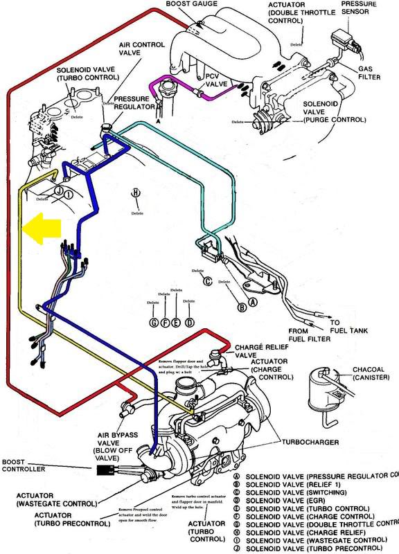
Vacuum Diagram For Single Turbo Rx7club Com Mazda Rx7 Forum
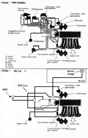
Engine Vacuum Hose Reduction 3000gt Stealth Wiki
Rre Vdo Boost Gauge Installation Instructions
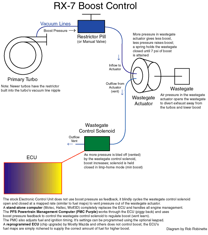
Boost Controller

Boost Gauge Installation Starwagon Info
External Wastegate Vacuum Line Routing Question Performance Modifications Volvospeed Forums
Robo
Boost Vacuum Leak What Is This Hose Volkswagen Passat Forum

Vacuum Reduction W Egr Help Diagram Inside Mitsubishi 3000gt Dodge Stealth Forum
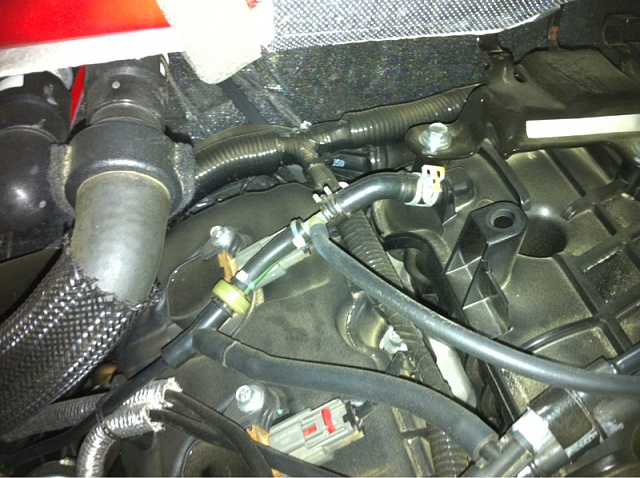
Boost Gauge Install Ford F150 Forum Community Of Ford Truck Fans
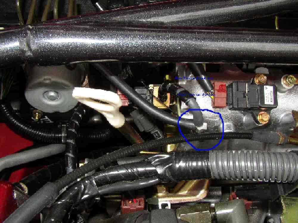
Boost Gauge Install Two Ways Evolutionm Mitsubishi Lancer And Lancer Evolution Community
How To Boost Gauge Install Chevrolet Cruze Forums
Digitl Boost Gauge Wiring Diagram Doesnt Make Sense Focus Fanatics Forum
Possible Sticky Turbo Vacuum Line Tap Location And Necessary Barbs T S Acura Rsx Ilx And Honda Ep3 Forum